

Remove the CPU module from the relay housing and set aside. Be certain to align the printed circuit board with the card guides in the housing. Always use antistatic bags for transporting modules Remove AC power and DC power from the PCD before removing, installing or wiring any of the PCD modules. Consult. What are the steps for safely removing and reinstalling a PLC CPU module? Safe removal and reinstallation of a PLC CPU module requires strict adherence to proper procedures to prevent equipment damage, data loss, or safety hazards. Consult the most recent PCD Instruction Book for details on programming the new CPU to suit your requirements. 0 or Modbus ASCII communications, protocol documentation is available. 1. 1 INTRODUCTION TO THE UR The GE Universal Relay (UR) series is a new generation of digital, modular, and multifunction equipment that is easily incorporated into automation systems, at both the station and enterprise levels. In particu-lar, one will find: General information with regard to design, configuration, and operation of SIPROTEC 4 devices are set out in the SIPROTEC 4 System Description /1/.
[PDF Version]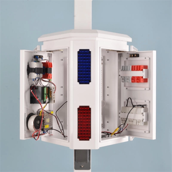
The article provides an overview of protective relaying principles and their applications for high-voltage power system components. It covers the protection methods for generators, transformers, buses, and transmission lines using various relay types to detect and isolate faults efficiently.
The TFT (Thin-Film Transistor) screens used in relay protection applications play a pivotal role in providing operators with clear, actionable information in real-time. Its modular design and powerful DIGSI 5 engineering tool provide tailored solutions. This reference design showcases a two-dimensional (2-D) Qt graphical user interface (GUI), which is typical for. presentation of protection and control relaying. The report will identify methodology behind these practices, present issues raised by the integration of microprocessor relays and the internal logic and external communication configurations, ying. The first numerical relays were released in 1985.
For testing high-voltage microcomputer protection devices, it is recommended to use a microcomputer relay protection tester capable of simultaneously outputting three-phase voltage and three-phase current, and equipped with timing function for digital inputs. Meet all test requirements on site. It can simulate various operating conditions of the power system, such as normal.

Phase comparison Technique (PCT) is a type of protection by which the quantities are conveyed through communication channels rather than wired interconnections of the relay input devices and it detects both phase and ground faults simultaneously. The phase comparison relaying principle is a line of differential relaying that compares the phase angles of the current entering one terminal of a transmission line with the phase angles of the current entering all the remote terminals of the same line. During normal conditions or through faults the currents. Why are seal-in and 52a contacts used in the dc control scheme? In a typical feeder OC protection scheme, what does the residual relay measure? Questions? 00000001 00000101 00001001 00100100 10010000 :. 51P1P Pickup 51P1C Pickup Type 51P1TD Time Dial 51P1RS Electromechanical Reset? (Y / N) 51P1CT. protective system, Components of Protection System. Sequence Components and Fault Analysis: sequence impedance, fault calculations, Single line to ground fault, Line to ground fault with Zf, Faults in Power syst ional relays, Distance relays, Differential relays. Those categories are directional comparison and phase comparison.
[PDF Version]
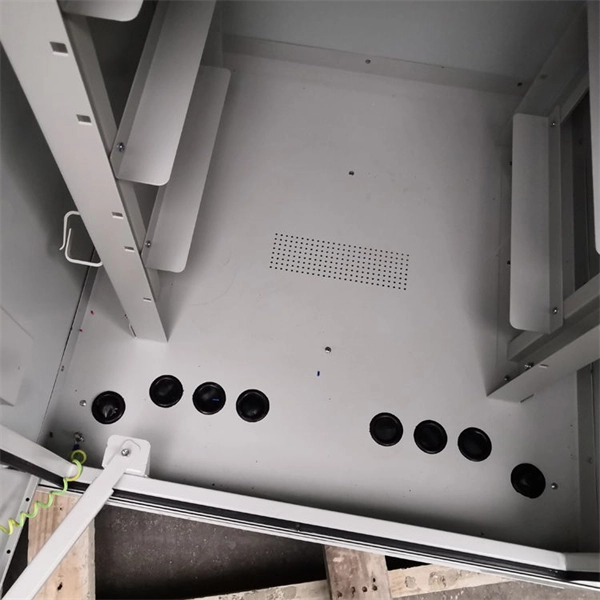
Its main purpose is to safeguard electrical equipment like transformers, generators, and transmission lines from damage due to abnormal conditions such as overloads, short circuits, or voltage imbalances. IEEE/IAS/I&CPSD Protection & Coordination WG Chair Jacobs Canada, Calgary, AB rasheek. com IEEE Southern Alberta Section PES/IAS Joint Chapter Technical Seminar - November 2016 Protective Relays - Technical Seminar Nov 2016 - Copyright: IEEE 2 Abstract: Protective relays and devices. Relay protection and automation (RPA) are critical systems in electrical networks. RPA automatically detect faults and emergency situations, then take action to disconnect the damaged section of the network to protect equipment and ensure stable and reliable power supply. What is Relay Protection. Selectivity is a mandatory requirement for all protection, but the importance of it depends on the application. While this is bad, It's not a. The rectangular devices are test connection blocks, used for testing and isolation of instrument transformer circuits.
[PDF Version]
Electromechanical protective relays operate by either, or. Unlike switching type electromechanical with fixed and usually ill-defined operating voltage thresholds and operating times, protective relays have well-established, selectable, and adjustable time and current (or other operating parameter) operating characteristics. Protection relays may use arrays of, shaded-pole, magnets, operating and restraint coils, solenoid-type operators, telephone-relay contacts.
Guidance on settings for the 132kV system is given in CP338, and for the 33kV and 11/6. Relay protection is essential to ensure the stability, reliability, and safety of electrical power systems. Protective relaying is the backbone of fault detection and system isolation in As transmission systems grow increasingly complex with integration of. This document states the Electricity North West Limited policy for protection for all high voltage systems. It covers standard codes, wiring practices, and norms for protecting generators, transformers, and lines, and provides detailed. Abstract: Covered in this recommended practice is the protection of bus and switchgear used in industrial and commercial power systems. Protection selectivity is partly considered in this report and could be also re-evaluated.
Protective relays are commonly referred to by standard device numbers. In the design of electrical power systems, the ANSI Standard Device Numbers denote what features a protective device supports (such as a relay or circuit breaker). These types of devices protect electrical systems and components from damage when an unwanted event occurs, such as an electrical. The protection and control devices in electrical equipment can be referred to by numbers, with appropriate suffix letters when necessary, according to the functions they perform. The device numbers are enumerated in ANSI / IEEE Standard C37.
Contact us for competitive quotes on any of our power communication and smart grid products
Get a Quote