
A strong fiber cable management system includes bend radius protection, cable routing paths, cable accessibility, and physical protection. As you work in the telecommunications field, you face complex challenges from rapid network growth and increasing data demands. Traditional methods can slow down your operations and increase the. Fiber monitoring refers to the continuous assessment of fiber quality through software tools and equipment that form an integrated optic fiber monitoring and management system. By leveraging sophisticated technology, cable monitoring systems provide insights into the health, performance, and security of your cables, helping you prevent issues before. The Fiber Monitoring System is a comprehensive platform for managing and maintaining fiber optic networks, utilizing DGPS and Cable Fault Locator technologies for precise fault detection and reduced restoration times. Continuous health is ensured through predictive maintenance and real-time.
[PDF Version]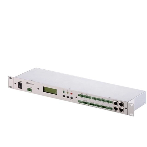
To test fibre splicer quality, begin by inspecting cleave angles and fibre cleanliness. Next, confirm arc calibration and alignment using the splicer's splice loss estimation. Follow up with OTDR or ILM testing to validate results. In this guide, we'll explore what splicing of fiber entails, why it's important, and dive into the key methods and tools. Fusion splicing is the process of fusing or welding two fibers together usually by an electric arc. Fusion splicing is the most widely used method of splicing as it provides for the lowest loss and least reflectance, as well as providing the strongest and most reliable joint between two fibers. fCONSTRUCTION QUALITY REQUIREMENTS FOR FTTP & SSP Work Orders This document provides Construction Technicians, Construction Managers, FTTP/SSP Vendors, and Inspectors with the essential information to ensure a quality build and to successfully pass an Outside Plant Inspection. This testing. This Applications Engineering Note (AEN 135) explains and recommends standard measurement methods for characterizing optical fiber system performance.
[PDF Version]
Fiber Monitoring System utilizes Differential GPS (DGPS) and Cable Fault Locator technologies to accurately detect and locate fiber optic cable degradations and cuts. This identifies anomalies and weakening signals that indicate potential damage. FOGrid is Sensor Lines' solution for cable integrity monitoring. By combining our advanced distributed fiber optic sensing technologies and our software suite with dedicated algorithms, it enables to: FOGrid is Sensor lines' comprehensive and easy to deploy solution to ensure a continuous real-time. Cable monitoring involves the continuous surveillance and management of cable systems to ensure their optimal functioning. By leveraging sophisticated technology, cable monitoring systems provide insights into the health, performance, and security of your cables, helping you prevent issues before. LANCIER Monitoring offers modular solutions for the monitoring of both active and passive fiber optic infrastructures. Continuous health is ensured through predictive maintenance and real-time.
[PDF Version]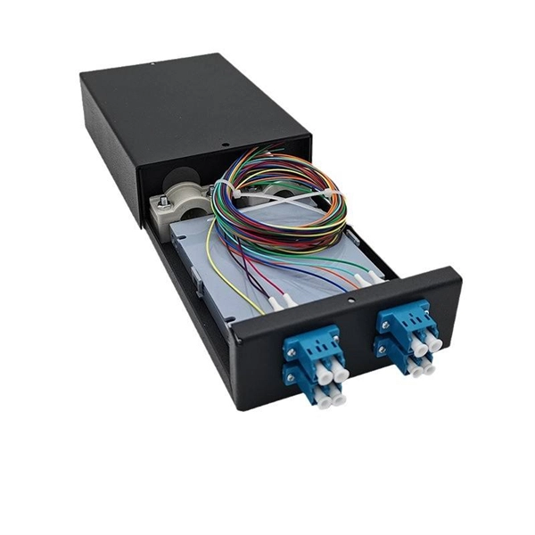
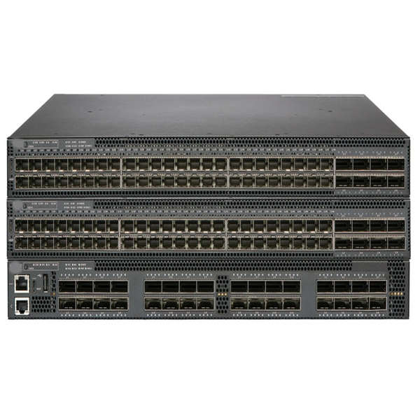
If you want your devices to access the internet, connect your network switch to your router or modem via Ethernet. Depending on your network brand, the steps might be a little different but we hope these guidelines will help you: 1. Here we take Huawei switches as an example. Configure the switch as the gateway for users, and realize mutual access. Connecting a network switch involves physically connecting devices using Ethernet cables and configuring them as needed, ultimately expanding your network connectivity and improving network performance. Connecting a network switch is a foundational skill for anyone managing a home or small business. Here's a step-by-step guide to help you seamlessly connect to a network switch: Choose the Right Cables: Before connecting devices to the switch, ensure that you have the appropriate cables. Ethernet cables, commonly known as patch cables, are the standard choice for connecting devices to a network. Can a Modem communicate and bring Internet access to any of the computers connected to the Hub/Switch? Hi everyone.
[PDF Version]
This duplex singlemode 9/125 OS2 cable is an ideal choice for 100G Ethernet applications up to 100 meters (328 feet) at 1310 nm. It is also backward compatible with 10 Gb, 25 Gb and 40 Gb networks, so you can future-proof your current application for an eventual upgrade to 100 Gb. The N370-100M-AR. Our 100m LC-LC armored fiber cable is featuring a stable armor layer that protects against bends, crushes, and harsh environments, ensuring reliable performance in even the most challenging installations. Low insertion loss, high return loss. Please enter your email address below to receive a password reset link. Buy LC fiber optic cable assemblies w/ best price, Ultra Low Loss/Armored/Switchable/Uniboot LC cables, Single mode & Multimode, Simplex & Duplex LC-LC Fiber Cables. Built with LC connectors on both.
The Cable Tray Fill Calculator calculates allowable fill percentage and maximum numbers of cables, considering tray dimensions, cable sizes, spacing, and standards. Follow these simple steps: Define Tray Dimensions: Enter the width and depth of your planned cable tray (in mm or inches). Select Fill Standard: Choose 40% for power cables (NEC compliant) or 50% for. Free cable tray fill calculator for electrical designers, plant electricians, and industrial maintenance teams who need to verify that cable installations comply with NEC Article 392 fill requirements. The calculation provides necessary information to avoid cable overfilling which produces dangerous situations such as overheating, mechanical damage and reduced. Use our **Cable Tray Fill Calculator** below to size your pathways correctly *before* you buy the materials. Cable management is the unsung hero of modern infrastructure. Track counts, diameters, and weight to validate configuration quickly with live feedback. NEC Article 392 limits fill ratios based on cable type and arrangement — single-layer or stacked — to ensure adequate ventilation, maintain current-carrying capacity, and provide space.
[PDF Version]
A simple solution is to combine a Corning USB “A to receptacle-A” USB 3. Optical™ Cables by Corning with a short, off-the-shelf jumper cable that has a USB “A” plug on one side and the particular connector your end device requires on the other. 0 A female port of the AOC Cable. Vielen Dank für den Kauf dieses Optischen USB 3. Es unterstützt größere Distanzen als herkömmliche Kupferkabel, ist deutlich flexibler und leichter und daher optimal. A workaround would be to connect the USB 3. Once connected, check the Windows Device Manager to verify the devices that have been successfully connected through the device. The USB active optical cables are designed to be compliant with SuperSpeed USB and SuperSpeed+ USB electrical specifications, offering seamless interoperability between existing USB 3. 1 hosts, hubs and devices, ensuring a trouble-free plug-and-play experience. The USB AOC address the. Connect the USC-CC32 Type C device connector to the USB Hub.
[PDF Version]Contact us for competitive quotes on any of our power communication and smart grid products
Get a Quote