
Optical attenuators are commonly used in, either to test power level margins by temporarily adding a calibrated amount of signal loss, or installed permanently to properly match transmitter and receiver levels. Sharp bends stress optic fibers and can cause losses. If a received signal is too strong a temporary fix is to wrap the cable around a pencil until the desired level of is achieved. However, such arrangements are unreliable, since the stressed fiber tends to.
Most spectrometer problems stem from three things: incorrect calibration, poor sample prep, or hardware wear. If your UV reading is drifting or results are inconsistent across runs, it's time to recalibrate using certified standards. BY isolating light and measuring its different wavelengths, they help astronomers analyze the chemical composition of celestial bodies light years away. Even if a spectrometer is properly maintained, wear and tear will mean that it may occasionally require troubleshooting to get it to work as expected. This guide outlines a structured approach to identifying, interpreting, and resolving common spectroscopic issues by linking visual symptoms. View and Download Ametek Spectro MIDEX original operating instructions online. Spectro MIDEX laboratory equipment pdf manual download. Spectrophotometer measurement errors are a common challenge in spectrophotometry, which can significantly affect the accuracy of results. Despite their widespread use, these instruments. Spectrometers are precision instruments used to measure the intensity of light across a spectrum.
[PDF Version]
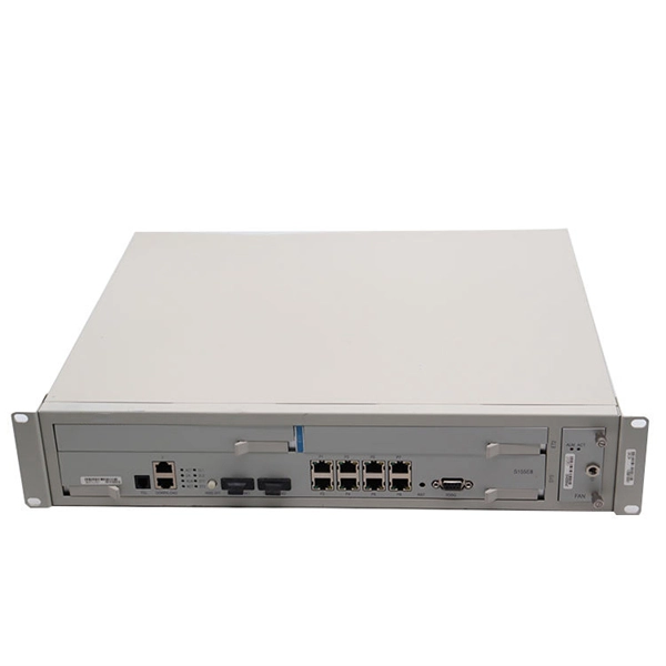
The optical receiver adds two types of noise namely thermal noise and shot noise. This application note provides an in-depth analysis of the complete receiver optical sensitivity and the potential power penalties related to the accumulation of random noise and inter-symbol interference (ISI) in both amplitude and timing. Ultimately, the noise influence on the signal will determine the system sensitivity. The challenge is to find a way to determine the. In the design of an optical receiver, it is vital that the module is capable of converting and shaping the optical signal while meeting or surpassing the maximum BER.
Synchronous Optical Networking (SONET) and Synchronous Digital Hierarchy (SDH) are standardized protocols that transfer multiple digital bit streams synchronously over optical fiber using lasers or highly coherent light from light-emitting diodes (LEDs). We demonstrate a switching contrast of 31. 9 dB, corresponding to a propagation distance of 14 mm, achieved by launching temporally synchronized SP-CP pairs into the fast core of the DCF with moderate inte -core asymmetry. It provides an expert-curated supplier directory, buyer-focused technical background information, and structured selection criteria to support professional procurement decisions. At low transmission rates, data can also be. Com-pared with weakly-coupled MCFs with independent cores, it can simultaneously realize higher spatial channel density and ultralow transmission loss using existing ultralow-loss single-mode fiber (SMF) core designs.
[PDF Version]
Wireless communication sends information across distances without physical conductors like cables or wires. The technology makes use of electromagnetic waves that travel through free space. RoF is not a new lab experiment; it is a mature and critical "enabling technology" experiencing a surge in demand, driven by the build-out of 5G infrastructure, LEO. This white paper introduces an FPGA-based analog video transmission system over fiber optic cable, ensuring long-distance, low-latency, and interference-free video transport while maintaining compatibility with existing analog video infrastructure. System Overview The proposed solution digitizes. RF over Fiber (RFoF) was developed to address the limitations of traditional coaxial cables in transmitting high-frequency RF signals over long distances with minimal signal loss and interference. Examples of Electromagnetic energy. Transmission media refers to the physical or wireless communication channel used to carry data signals from one device to another within a computer network.
[PDF Version]
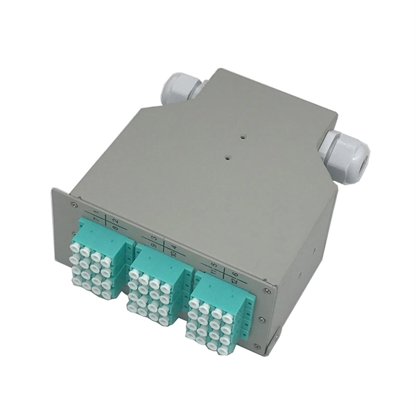
At its core, a fiber optic splitter relies on the principles of light reflection, refraction, and waveguiding to divide signals. The optical network system uses an optical signal coupled to the branch distribution. Its primary role is in Passive Optical Networks (PON), which are the foundation of. Whether you're a network engineer designing a PON (Passive Optical Network) or a homeowner curious about how your fiber connection works, understanding splitters is essential for grasping the backbone of modern connectivity.
Contact us for competitive quotes on any of our power communication and smart grid products
Get a Quote